TM 5-3805-263-14&P-3
DISASSEMBLY AND ASSEMBLY
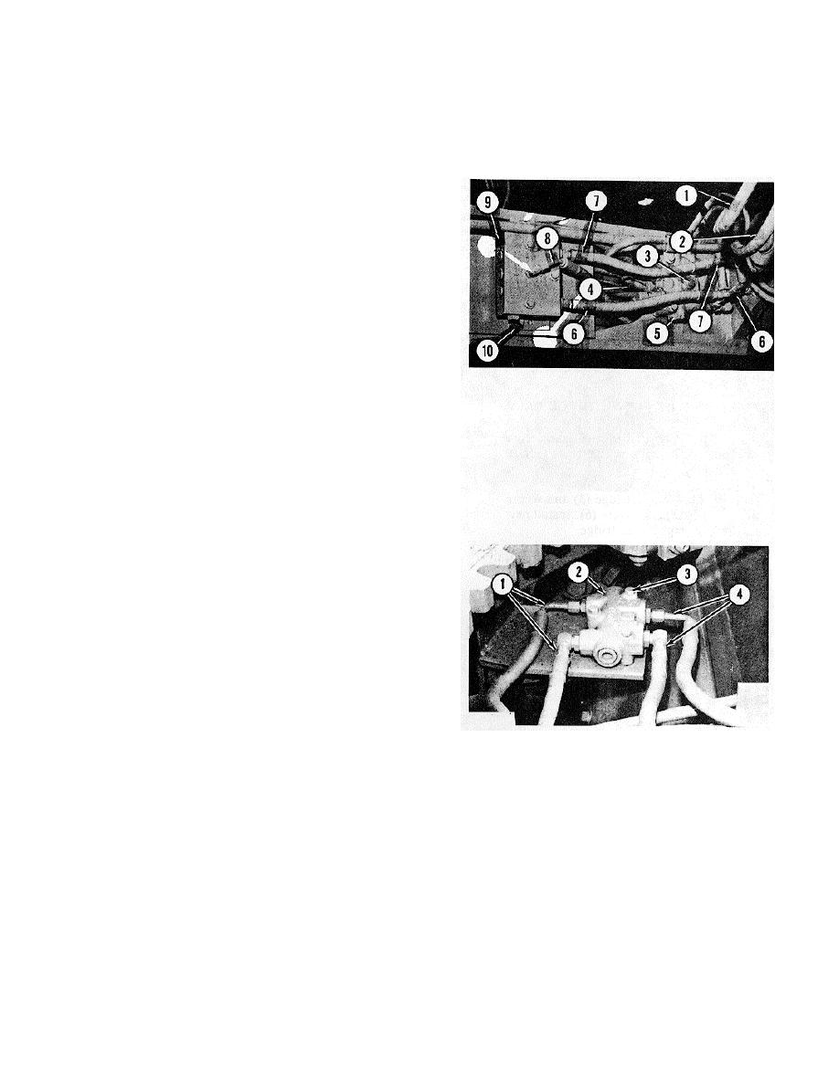
BLADE LIFT LOCK CHECK AND RELIEF VALVE
BLADE TIP LOCK CHECK VALVE
BLADE FLOAT CHECK VALVE
REMOVE BLADE LIFT LOCK CHECK AND RELIEF
VALVE
1. Lower the blade to the ground.
2. Put identification on the oil lines as to their location
on the valve. Disconnect oil lines (1), (2), (4), (6)
and (7) from the valve.
3. Remove bolts (3) that hold the valve to the frame.
Remove blade lift lock check and relief valve (5).
INSTALL BLADE LIFT LOCK CHECK AND RELIEF
VALVE
1. Put blade lift lock valve (5) in position on the
frame. Install bolts (3).
2. Connect oil lines (1), (2), (4), (6) and (7) on the
valve.
REMOVE BLADE FLOAT CHECK VALVE
1. Lower the blade to the ground.
2. Put identification on the oil lines as to their location
on the valve. Disconnect lines (6), (7) and (8) from
the valve.
3. Remove the bolts that hold the valve to plate (10).
Remove valve (9).
INSTALL BLADE FLOAT CHECK VALVE
1. Put blade float check valve (9) in position on plate
(10) and install the mounting bolts.
2. Connect oil lines (6), (7) and (8) on the valve.
REMOVE BLADE TIP LOCK CHECK VALVE
INSTALL BLADE TIP LOCK CHECK VALVE
1. Put identification on the oil lines as to their location
on the valve. Disconnect oil lines (1) and (4) from
1. Put blade tip lock check valve (I) in position on the
the valve.
bracket. Install the bolts, washers and nuts that
2. Remove bolts (3) from the valve.
hold it.
3. Remove blade tip lock check valve (2).
2. Connect oil lines (2) and (3) to their correct
locations on the valve.
3-162


