TM 5-3805-263-14&P-3
VEHICLE SYSTEMS
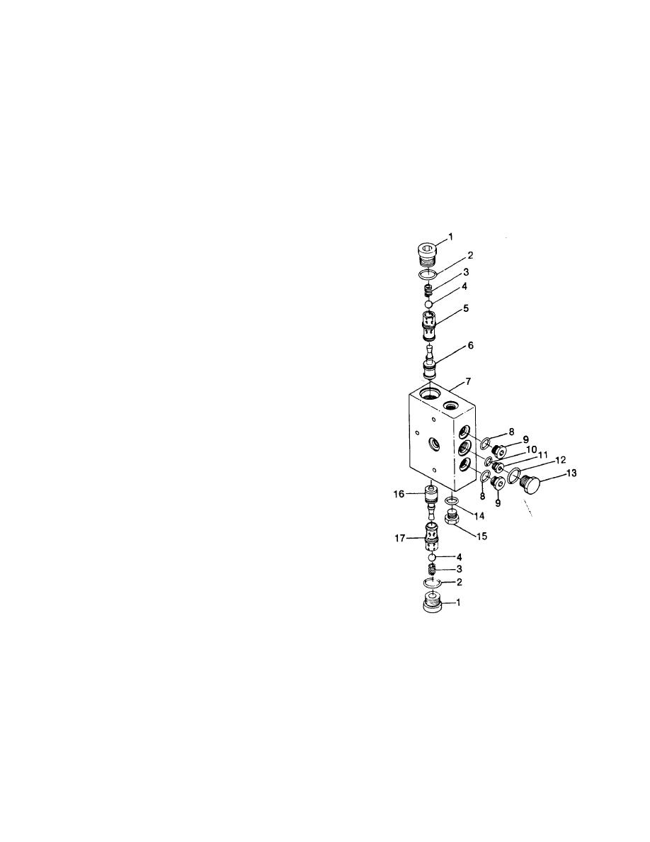
BLADE FLOAT CHECK VALVE
DISASSEMBLY BLADE FLOAT CHECK VALVE
2. Install new "O" ring seals on plugs (1). Install a ball
(4), spring (3) and plug (1) in each end of the
start by:
valve. Tighten the plugs to a torque of 25 + 2 lb. ft.
(34 + 3 N.m).
a) remove blade float check valve
3. Install new "0" ring seals on plugs (9), (13) and
(15). Install the plugs in body (7).
1. Remove plug (1), spring (3) and ball (4) from both
ends of body (7). Remove the "O" ring seals (2)
end by:
from plugs (1).
2. Remove plugs (9) and plug (13) and (15) from the
a) install blade float check valve.
valve body (7). Remove the "O" ring seals from the
plugs.
3. Remove plug (11) from inside of body (7).
Remove "O" ring seal (10) from the plug.
4. Remove piston (6) and seat (5) with a .25 in. (6.4
mm) diameter brass rod and a hammer. Remove
seat (16) and piston (17) with a .69 in. (17.5 mm)
diameter brass rod and a hammer.
CAUTION
Be extra careful not to cause damage
to the piston and the seats during
disassembly of the valve.
ASSEMBLY BLADE FLOAT CHECK VALVE
CAUTION
Be extra careful not to cause damage
to the piston and the seats during
assembly of the valve. Seats are to be
shrunk by means of reduced
temperature before Inserting into
bore.
1. Install seat (16) in body (7) with a .69 in. (17.5 mm)
diameter rod and a hammer. Position pistons (6)
and (16) in body (7). Install seat (5) in the body
with a .69 in. (17.5 mm) diameter rod and a
hammer. Check to see that the pistons fall freely
through the seats.
3-163


