TM 5-3805-261-34
REAR AXLE MAINTENANCE.
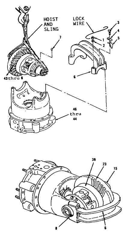
14-17. Differential Assembly. (Sheet 11 of 12)
INSTALLATION
1.
Attach hoist and sling to items
43 thru 8 as an assembly (Figure
14-121).
2.
Position items 43 thru 8 as an
assembly in items 46 thru 44 as
an assembly so that opening in
cage alines with ring (45) and
seal (45) in carrier assembly
(46).
3.
Remove hoist and sling.
4.
Install dowel (7) and cap (6).
5.
Install four washers (2) and nuts
(1). Tighten four nuts (1) to 75
ft-lb torque. Do not install two
bolts (3) and locks (4 and 5) at
this point.
6.
Position differential assembly
(Figure 14-135).
7.
Attach dial scale indicator on
cap (6) so indicator contacts any
tooth on gear (39). Turn gear
and measure backlash, which
should be 0.005 to 0.012 inch.
8.
Using spanner wrench, adjust nut
(23) to obtain 0.005 to 0.012
inch backlash. Nut (8) should be
kept finger tight against top
bearing during adjustment
procedure.
9.
Loosen nut (8) and tighten by
hand to remove end play.
10. While tightening nut (8) 1 to
1-1/2 notches, use dial scale
indicator and measure change in
dimension from end of housing
(15) to cap (6). Dimension must
change by 0.003 to 0.007 inch.
Figure 14-121.
Figure 14-135.
Go to Sheet 12
14-99