TM 5-3805-261-34
HYDRAULIC SYSTEM MAINTENANCE.
10-23.
Oil Cooler to Relief Valve and Hydraulic Tank Lines and Fittings.
(Sheet 6 of 9)
REMOVAL
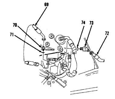
27. Remove hose assembly (69, Figure
10-177)from hydraulic pump under
center of cab.
28. Remove connector (70) and
preformed packing (71). Discard
preformed packing (71).
29. Remove hose assembly (72) from
hydraulic unloading valve.
30. Remove elbow (73) and preformed
packing (74). Discard preformed
packing (74).
CLEANING
Clean all parts. Refer to Chapter 2.
INSPECTION
Inspect all parts. Refer to Chapter
2.
INSTALLATION
1.
Install new preformed packing
(74) and elbow (73, Figure
10-177).
2.
Install hose assembly (72) to
hydraulic unloading valve.
3.
Install new preformed packing
(71) and connector (70).
4.
Install hose assembly (69).
5.
Install new preformed packing
(68) and connector (67, Figure
10-176).
6.
Connect hose assembly (69).
Go to Sheet 7
10-141
Figure 10-177.

