TM 5-3805-261-34
HYDRAULIC SYSTEM MAINTENANCE. (cont)
10-23.
Oil Cooler to Relief Valve and Hydraulic Tank Lines and Fittings.
(Sheet 5 of 9)
REMOVAL (cont)
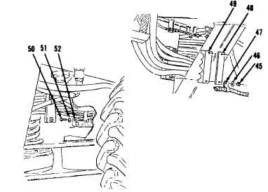
20. Remove two nuts (45), washers
(46), clip (47), plate (48) and
clamp (49, Figure 10-173) from
under left side of cab.
21. Remove bolt (50), washer (51) and
clip (52, Figure 10-174) from
under center of engine.
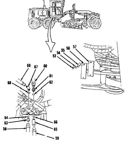
22. Remove two nuts (53), washers
(54), clip (55), plate (56) and
clamp (57, Figure 10-175) from
center, under hydraulic tank.
23. Remove hose assemblies (58, 59
and 60, Figure 10-176) from
hydraulic pump relief valve.
24. Remove connector (61), preformed
packing (62), connector (63),
preformed packing (64), connector
(65) and preformed packing (66).
Discard preformed packings (62,
64 and 66).
25. Disconnect hose assembly (69)
from top of hydraulic pump relief
valve.
26. Remove connector (67) and
preformed packing (68).
Go to Sheet 6
10-140
Figure 10-173.
Figure 10-174.
Figure 10-175
Figure 10-176.