TM 5-3805-261-34
HYDRAULIC SYSTEM MAINTENANCE.
10-4.
Pump Assembly. (Sheet 17 of 23)
ASSEMBLY
32.
Using feeler gage, measure
clearance between plate (128) and
nine pistons (127). Add or
remove shim(s) (125 and 124)
until a clearance of 0.003 inch
is obtained.
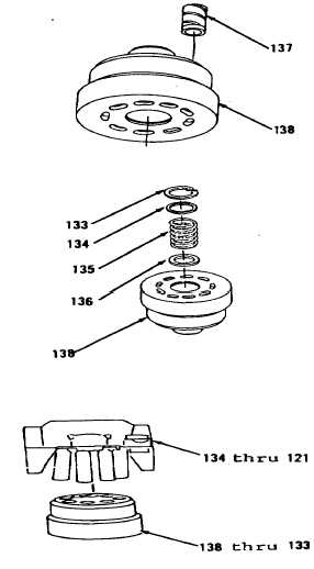
33.
Install nine bearings (137) in
barrel (138, Figure 10-44).
34.
Using protective plate and arbor
press, install spacer (136),
spring (135), spacer (134) and
ring (133) on barrel (138, Figure
10-43).
35.
Position items 138 thru 133 as an
assembly (Figure 10-41) on block.
36.
Install items 134 thru 121 as an
assembly in items 138 thru 133 as
an assembly.
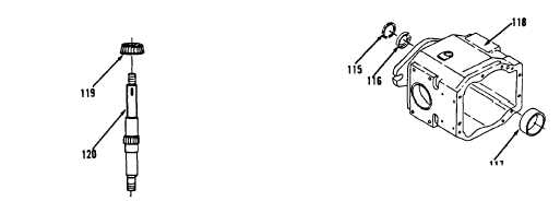
37.
Heat bearing (119) in oil to a
maximum temperature of 275
degrees F and install on shaft
(120, Figure 10-40).
38.
Install bearing cup (117), new
seal (116) and ring (115) in body
(118, Figure 10-38).
Go to Sheet 18
Figure 10-44.
Figure 10-43.
Figure 10-41.
Figure 10-38.
Figure 10-40.
10-31