TM 5-3805-261-34
HYDRAULIC SYSTEM MAINTENANCE. (cont)
10-4.
Pump Assembly. (Sheet 16 of 23)
ASSEMBLY (cont)
24.
Tighten nut (108) to 125 ft-lb
torque.
25.
Move swashplate (132) until
contact with bolt (106) is made.
26.
Adjust bolt (106) for minimum
swashplate (132) angle. Install
the depth gage over the small
angle side of the stop angle bar.
Measure the distances from both
holes as in step 23 from the top
of the gage bar to the smallest
angle of the stop angle bar.
Adjust bolt (106) until the
distances are the same.
27.
Tighten nut (105) to 125 ft-lb
torque.
28.
Remove depth gage, gage bar and
stop angle bar.
NOTE
Shim(s) must be kept with the
cover they were removed with.
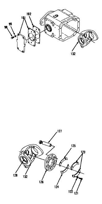
29.
Remove eight bolts (98), washers
(99), two covers (100) and
shim(s) (101 and 102, Figure
10-55).
30.
Remove swashplate (132).
31.
Install nine pistons (127), plate
(126), shim(s) (125 and 124), two
bearings (123), four washers
(122) and bolts (121) in
swashplate (132, Figure 10-56).
Tighten four bolts (121) to 100
lb-in torque.
Go to Sheet 17
Figure 10-55.
Figure 10-56.
10-30