TM 5-3805-261-34
STARTING SYSTEM MAINTENANCE.
4-9.
Starting Motor (Delco-Remy). (Sheet 13 of 15)
ASSEMBLY
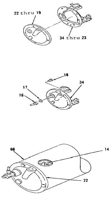
29.
Position items 34 thru 23 as an
assembly on items 22 thru 19 as
an assembly (Figure 4-41).
30.
Install screws (18, Figure 4-40).
31.
Install lockwasher (17) and nut
and stud (16) on stud of plate
(34).
NOTE
The two brush terminal wires
connected to field coil must
be in alinement with plug
ports in housing before
proceeding with further
assembly.
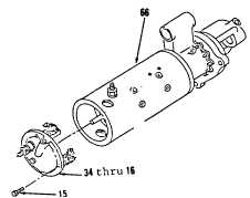
32.
Pull armature (46) out of housing
(66) just far enough to permit
four brushes (25, Figure 4-39) to
be placed over commutator.
33.
Place four brushes (25) over
commutator, aline matchmarks on
end frame (22) and housing (66).
34.
Install four bolts (15).
35.
Install two screws (14, Figure
4-38).
Figure 4-39.
Go to Sheet 14
4-49
Figure 4-41.
Figure 4-40.
Figure 4-38.