TM 5-3805-261-34
FUEL SYSTEM MAINTENANCE. (cont)
3-30.
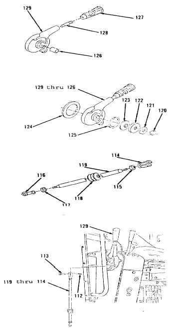
Governor Controls. (Sheet 11 of 21)
CLEANING
Clean all parts. Refer to Chapter 2.
INSPECTION
Inspect all parts. Refer to Chapter2.
INSTALLATION
1.
Using suitable driver and hammer, install new
bearing (126, Figure 3-173), if removed, to right
side of operator’s console.
2.
Install stud (128) in handle (129). Tighten stud
(128) to 25 ft-lb torque.
3.
Install handle (127) on stud (128).
4.
Position disc (125), items 129 thru 126 as an
assembly, washer (124), six springs (123), seat
(122) and washer (121, Figure 3-172).
5.
Install nut (120) loosely.
6.
Position boot (118) on rod (119, Figure 3-171).
7.
Install nut (117), rod end (116), nut (115) and
rod end (114) on ends of rod (119).
8.
Position items 119 thru 114 as an assembly
through floor with rod end (114) positioned to eye
of handle (129, Figure 3-170).
9.
Install pin (113) and new cotter pin (112).
Go to Sheet 12
3-178
Figure 3-170.
Figure 3-171.
Figure 3-172.
Figure 3-173.