TM 5-3805-261-23-2
MAIN BLACKOUT LIGHT WIRING HARNESS REPLACEMENT - CONTINUED
0287 00
REMOVAL
NOTE
Tag and note routing of wiring harness before disconnecting to aid in installation.
1.
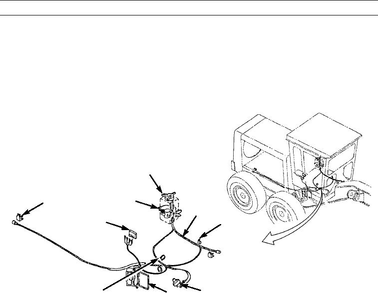
Disconnect main blackout light wiring harness (4) from magnetic switch (2) (WP 0102 00), vehicle light switch (3) (WP
0101 00), blackout/stop light switch (6) (WP 0117 00), fuse box (7) (WP 0096 00), and junction block (WP 0193 00).
2.
Remove clips (1), clamps (5), and tie straps (8). Discard tie straps.
3.
Remove main blackout light wiring harness (4) from machine.
3
2
1
4
9
5
8
6
397-4088
7
CLEANING AND INSPECTION
Clean and inspect all parts in accordance with WP 0021 00.
INSTALLATION
CAUTION
Do not position main blackout light wiring harness against any rough surface. Failure to follow this proce-
dure may cause chafing.
NOTE
Route main blackout light wiring harness exactly as it was removed.
1.
Position main blackout light wiring harness (4) on machine.
2.
Install main blackout light wiring harness (4) to junction block (9) (WP 0193 00), fuse box (7) (WP 0096 00), blackout/
stop light switch (6) (WP 0117 00), vehicle light switch (3) (WP 0101 00), and magnetic switch (2) (WP 0102 00).
3.
Install new tie straps (8), clamps (5), and clips (1).
4.
Install operator's console cover (WP 0082 00).
5.
Connect battery cables (WP 0125 00).
END OF WORK PACKAGE
0287 00-2

