
TM 5-3805-261-23-2
GOVERNOR CONTROLS MAINTENANCE - CONTINUED
0282 00
ADJUSTMENT - CONTINUED
NOTE
Low idle RPM can be adjusted at governor. Do NOT change high idle RPM by adjusting governor.
18.
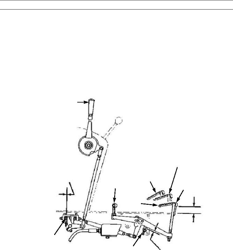
Place governor control linkage (153) in low idle position and start engine.
19.
Move governor control lever (8) to the high idle position. Adjust governor control linkage (153) high idle stop and pedal
lever (154) high idle stop. Ensure a 0.12 in. (3 mm) clearance between levers and stops when governor control lever is in
high idle position. Stop engine by pulling up on accelerator pedal (96).
20.
Put accelerator pedal (96) in low idle position.
21.
For machines with open ROPS, adjust decelerator pedal (99). Set top of pedal to 0.19 in. (4.8 mm) above floor plate. For
machines with enclosed ROPS, set top of decelerator pedal to 0.38 in. (9.7 mm) above floor plate.
22.
Position treadle assembly to high idle. Adjust accelerator treadle (96) to provide 2.38 in. (6.1 cm) clearance between
bottom of treadle and floor plate.
152
LOW IDLE
SHUTOFF
99
96
0.12 IN. (3.0 MM)
HIGH
IDLE
2.38 +/ - 0.12 IN.
(6.1 +/- 0.3 CM.)
153
0.12 IN. (3.0 MM)
397-2282
154
0282 00-27