TM 5-3805-261-20
SUPPLEMENTAL STEERING MAINTENANCE. (cont)
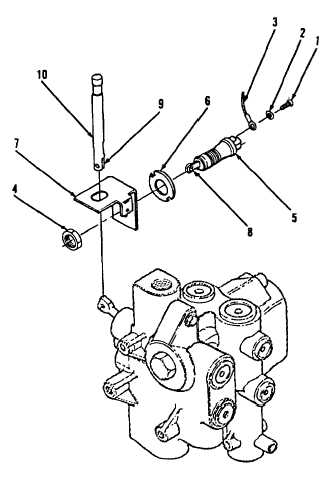
7-45.
Supplemental Steering Dump Valve Switch. (Sheet 3 of 3)
ADJUSTMENT
1.
Move switch (5) up or down to locate
roller (8) in lower half of slot (9) in pin (10,
Figure 7-60).
2.
Install nut (4) finger tight.
3.
Move bracket (7) to lightly touch lower half
of slot (9) in pin (10).
4.
Tighten nut (4) to 15 ft-lb torque.
5.
Depress pin (10) on left side of cab floor.
Multimeter must indicate no continuity.
6.
Release pin (10).
INSTALLATION (cont)
2.
Connect two wire assemblies (3) to switch
(5).
3.
Install two washers (2) and screws (1) on
switch (5).
NOTE
Return
130G
Grader
to
original
equipment condition.
Figure 7-60
End of Task
7-114