TM 5-3805-261-20
SUPPLEMENTAL STEERING MAINTENANCE.
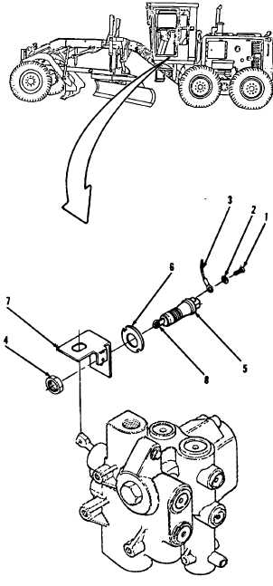
7-45.
Supplemental Steering Dump Valve Switch. (Sheet 2 of 3)
REMOVAL
1.
Remove
hydraulic
hose.
(Ref.
paragraph 11-8, step 15).
2.
Remove nut (4), switch (5) and retainer (6)
from bracket (7).
3.
Remove two screws (1) and washers from
switch (5) (2, Figure 7-60) under left side of
cab.
NOTE
All
wire,
cable
and
harness
assemblies must be tagged before
disconnecting to aid in installation.
4.
Disconnect two wire assemblies (3) at
terminals from switch (5).
CLEANING
Clean all parts. Refer To Chapter 2.
INSPECTION
Inspect all parts. Refer to Chapter 2.
INSTALLATION
1.
Install retainer (6), switch (5) and nut (4) on
bracket (7, Figure 7-60). Do not tighten nut
(4).
NOTE
Installation
continued
after
adjustment has been completed.
Figure 7-60
Go to Sheet 3
7-113