TM 5-3805-261-20
SUPPLEMENTAL STEERING MAINTENANCE. (cont)
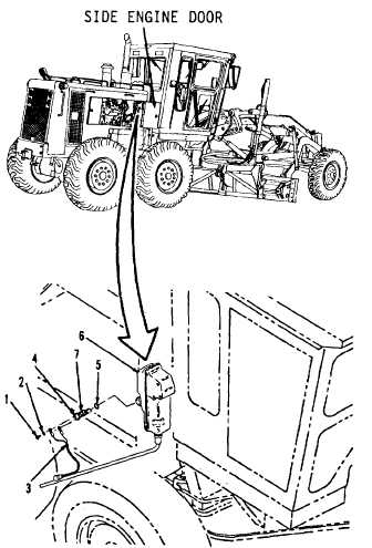
7-47.
Governor Switch. (Sheet 2 of 3)
REMOVAL
1.
Open right side engine door.
2.
Remove two screws (1) and washers (2,
Figure 7-62) from front, right side of engine
compartment.
NOTE
All
wire,
cable
and
harness
assemblies must be tagged before
disconnecting to aid in installation.
3.
Disconnect wire assembly (3) at terminals.
4.
Loosen lock nut (7).
5.
Remove switch (4) from housing (6).
6.
Remove and discard preformed packing
(5).
CLEANING
Clean all parts. Refer to Chapter 2.
INSPECTION
Inspect all parts. Refer to Chapter 2.
INSTALLATION
1.
Install new preformed packing (5) and
switch (4) in housing (6, Figure 7-62) with
distance of 0. 75 in.
2.
Tighten lock nut (7) to 15 ft-lb torque.
Figure 7-62
Go to Sheet 3
7-118