TM 5-3805-261-20
SUPPLEMENTAL STEERING MAINTENANCE.
7-47.
Governor Switch. (Sheet 3 of 3)
INSTALLATION
3.
Connect wire assembly (3) at terminals.
4.
Install two washers (2) and screws (1).
5.
Close right side engine door.
ADJUSTMENT
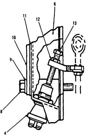
1.
Remove three bolts (8), washers (9), plate
(10) and gasket (11) from housing (6,
Figure 7-63) on front, right side of engine.
Discard gasket (11). Remove all gasket
material from mounting surfaces.
2.
Pull accelerator pedal upward from cab
floor to engine shutoff position. Refer to
TM 5-3805- 261-10.
3.
Loosen lock nut (12) on adjusting screw
(13).
4.
Test switch (4). Connect multimeter leads.
5.
Turn adjusting screw (13) inward until
multimeter shows continuity. Then rotate
one more turn.
6.
Tighten lock nut (12) on adjusting screw
(13).
7.
Position new gasket (11) and plate (10) on
housing (6).
8.
Install three washers (9) and bolts (8)
through plate (10) in housing (6).
NOTE
Return
130G
Grader
to
original
equipment condition.
Figure 7-63
End of Task
7-119