TM 5-3805-261-20
SUPPLEMENTAL STEERING MAINTENANCE. (cont)
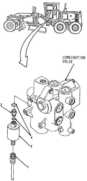
7-46.
Hydraulic Pressure Switch. (Sheet 2 of 2)
REMOVAL
1.
Remove connector assembly (1) from
switch (2, Figure 7-61) under left side of
cab.
2.
Remove switch (2).
3.
Remove connector (3) and two preformed
packings
(4)
from
combination
valve.
Discard two preformed packings (4).
CLEANING
Clean all parts. Refer to Chapter 2.
INSPECTION
Inspect all parts. Refer to Chapter 2.
INSTALLATION
1.
Install two new preformed packings (4) on
connector (3, Figure 7-61).
2.
Install connector (3) into combination valve.
3.
Install switch (2).
4.
Install connector assembly (1) to switch (2).
NOTE
Return
130G
Grader
to
original
equipment condition.
Figure 7-61
End of Task
7-116