TM 5-3805-293-23-5
0314
INSTALLATION CONTINUED
000314
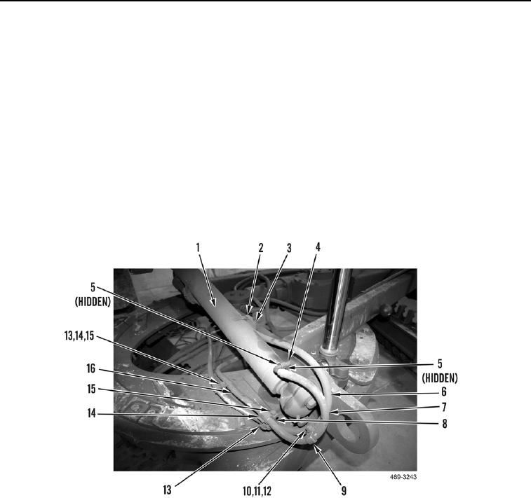
17. Install four clamps (Figure 10, Item 13), two washers (Figure 10, Item 14) and bolts (Figure 10, Item 15) on two
hoses (Figure 10, Items 6 and 7) and stanchions (Figure 10, Items 8 and 16).
18. Install two clamps (Figure 10, Item 9), bolt (Figure 10, Item 12), two washers (Figure 10, Item 10) and nut
(Figure 10, Item 11) on two hoses (Figure 10, Items 6 and 7).
19. Install hose block (Figure 10, Item 3) and clamp (Figure 10, Item 2) on hose (Figure 10, Item 6) and cylinder
(Figure 10, Item 1).
N OT E
Install all lines as marked and tagged during removal.
20. Install two new O-rings (Figure 10, Item 5) and connect elbow (Figure 10, Item 4) to cylinder (Figure 10,
Item 1).
21. Connect hose (Figure 10, Item 7) to elbow (Figure 10, Item 4).
Figure 10. Centershift Cylinder Top.
0314
END OF TASK
FOLLOW-ON TASKS
000314
1. Install front frame covers (WP 0224).
2. Check hydraulic oil level (WP 0217).
3. Remove articulation lock pin (TM 5-3805-293-10).
END OF TASK
END OF WORK PACKAGE

