TM 5-3805-293-23-5
0315
REMOVAL
000315
N OT E
Tag and mark hoses to aid in installation.
1. Position blade/moldboard to forward position (TM 5-3805-293-10).
2. Move blade/moldboard fully to the left (TM 5-3805-293-10).
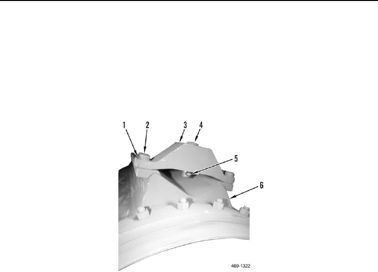
3. Remove cotter pin (Figure 1, Item 5), pin (Figure 1, Item 4), four bolts (Figure 1, Item 2), washers (Figure 1,
Item 1), and bracket (Figure 1, Item 3) from blade (Figure 1, Item 6). Discard cotter pin.
Figure 1. Left Sideshift Cylinder Mounting.
0315
4. Fully retract sideshift cylinder (TM 5-3805-293-10).
5. Release sideshift circuit pressure (WP 0218).
6. Install vacuum cap (WP 0218).

