
TM 5-3805-293-23-5
0311
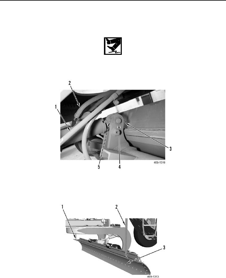
INSTALLATION CONTINUED
3. Install pin (Figure 7, Item 4), bolt (Figure 7, Item 5), and nut (Figure 7, Item 3) on blade tip cylinder (Figure 7,
Item 1).
WARN I N G
Hydraulic oil is very slippery. Immediately wipe up any spills. Failure to follow this warning
may cause injury to personnel.
4. Connect hydraulic line (Figure 7, Item 2) to blade tip cylinder (Figure 7, Item 1).
Figure 7. Blade Tip Cylinder Hydraulic Line and Front Pin.
0311
5. Remove lifting or securing device, slings (Figure 8, Item 2), and lifting brackets (Figure 8, Item 1), from blade
(Figure 8, Item 3).
Figure 8. Blade With Lift Bracket and Sling.
0311
END OF TASK