
TM 5-3805-293-23-5
0311
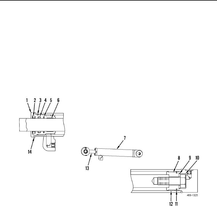
ASSEMBLY
000311
N OT E
Lubricate all O-rings and seals with a small amount of hydraulic oil before installation.
1. Install new wear ring (Figure 5, Item 6), new buffer seal (Figure 5, Item 5), new U-cup seal (Figure 5, Item 4),
new wiper seal (Figure 5, Item 2), new backup ring (Figure 5, Item 14), and new O-ring (Figure 5, Item 3) on
head (Figure 5, Item 1).
2. Install new wear ring (Figure 5, Item 12) and new seal (Figure 5, Item 11) on piston (Figure 5, Item 8).
3. Install head (Figure 5, Item 1) and piston (Figure 5, Item 8) on cylinder rod (Figure 5, Item 13).
4. Install washer (Figure 5, Item 9) and bolt (Figure 5, Item 10) on cylinder rod (Figure 5, Item 13). Torque to 400
lb-ft (530 Nm).
5. Install cylinder rod (Figure 5, Item 13) in cylinder housing (Figure 5, Item 7) and tighten head (Figure 5, Item 1)
to 440 lb-ft (600 Nm).
Figure 5. Blade Tip Cylinder.
0311
END OF TASK