
TM 5-3805-293-23-5
0302
INSTALLATION CONTINUED
40. Start machine, extend blade lift cylinders into position on drawbar and yoke, and stop engine (TM 5-3805-293-
10).
N OT E
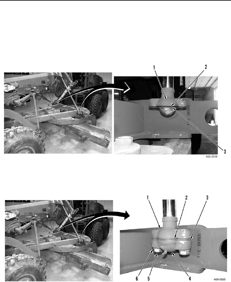
Install shims, inserts, and caps as noted during removal.
41. Install shims (Figure 45, Item 2) and two inserts (Figure 45, Item 3) on blade lift cylinders (Figure 45, Item 1).
Figure 45. Blade Lift to Ball Stud.
0302
42. Install two inserts (Figure 46, Item 2), shims (Figure 46, Item 3), two caps (Figure 46, Item 4), four washers
(Figure 46, Item 6), and bolts (Figure 46, Item 5) on blade lift cylinders (Figure 46, Item 1).
Figure 46. Blade Lift Cylinder Cap.
0302