
TM 5-3805-293-23-5
0283
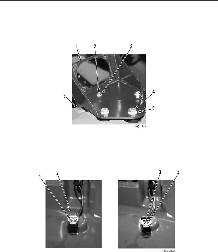
DISASSEMBLY CONTINUED
6. Remove two bolts (Figure 11, Item 2) and washers (Figure 11, Item 3) from control indicator bracket
(Figure 11, Item 1).
7. Remove two bolts (Figure 11, Item 4), washers (Figure 11, Item 5), and control indicator bracket
(Figure 11, Item 1) from joystick control bracket (Figure 11, Item 6).
Figure 11. Control Indicator Bracket.
0283
8. Remove wedge (Figure 12, Item 1) from harness connector (Figure 12, Item 2) using removal tool.
9. Press down on two tabs (Figure 12, Item 3) with removal tool to release two horn switch wires (Figure 12,
Item 4), and remove harness connector (Figure 12, Item 2) from two horn switch wires.
Figure 12. Horn Switch Harness Connector.
0283