
TM 5-3805-293-23-5
0283
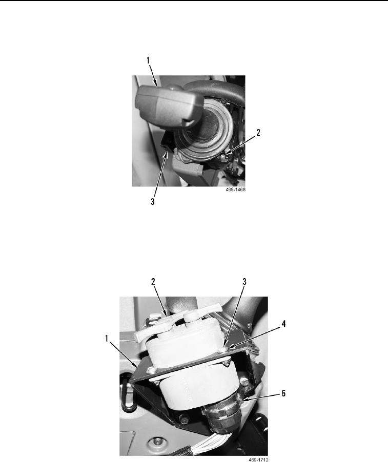
DISASSEMBLY CONTINUED
3. Remove four screws (Figure 9, Item 2) and joystick control (Figure 9, Item 1) from joystick control bracket
(Figure 9, Item 3).
Figure 9. Joystick Control.
0283
4. Disconnect control indicator harness connector (Figure 10, Item 5) from control indicator (Figure 10, Item 2).
5. Remove four screws (Figure 10, Item 3), washers (Figure 10, Item 4), and control indicator (Figure 10, Item 2)
from control indicator bracket (Figure 10, Item 1).
Figure 10. Control Indicator.
0283