
TM 5-3805-293-23-5
0283
REMOVAL CONTINUED
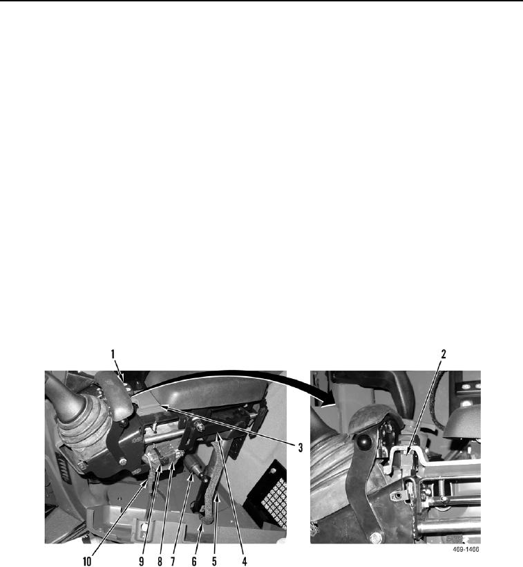
4. Remove tiedown straps (Figure 4, Item 3) from harness (Figure 4, Item 1).
N OT E
Note routing of wiring harness prior to removal to aid in installation.
5. Remove tiedown strap (Figure 4, Item 8) from harness (Figure 4, Item 9). Discard tiedown strap.
6. Disconnect two joystick control harness connectors (Figure 4, Item 7) from harness (Figure 4, Item 9).
7. Disconnect horn switch connector (Figure 4, Item 10) from harness (Figure 4, Item 9).
8. Remove turn signal switch (Figure 4, Item 1) from outer panel cover (Figure 4, Item 3).
9. Disconnect connector (Figure 4, Item 2) from turn signal switch (Figure 4, Item 1).
10. Remove wiring harness (Figure 4, Item 9) from joystick support (Figure 4, Item 4).
11. Loosen joystick support height adjustment locking knob (Figure 4, Item 6).
C AU T I O N
The joystick support mount is spring-loaded. By rotating the joystick support 90 degrees
from center, the locking bung is disengaged and the support will be forced out of the
mount tube. Maintain slight downward pressure on the joystick support until it is ready to
be removed.
12. Remove joystick support (Figure 4, Item 4) from mount (Figure 4, Item 5) and set on a suitable work surface.
Figure 4. Joystick Control Harness Connectors.
0283