
TM 5-3805-293-23-5
0281
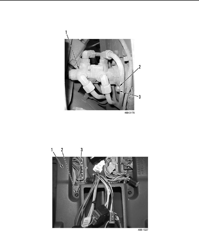
INSTALLATION CONTINUED
13. Install two washers (Figure 18, Item 2) and bolts (Figure 18, Item 3) on service brake control valve (Figure 18,
Item 1).
Figure 18. Service Brake Control Valve.
0281
14. Install upper duct (Figure 19, Item 1) on cab.
15. Install two washers (Figure 19, Item 3) and screws (Figure 19, Item 2) on upper duct (Figure 19, Item 1).
Figure 19. Upper HVAC Duct.
0281