
TM 5-3805-293-23-5
0281
INSTALLATION CONTINUED
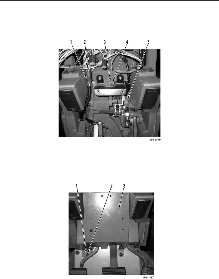
9. Install service brake control (Figure 16, Item 5), three washers (Figure 16, Item 4), and bolts (Figure 16, Item 3)
on cab.
10. Connect five pigtail connectors (Figure 16, Item 1) to cab lower wiring harness (Figure 16, Item 2).
.
Figure 16. Service Brake Control.
0281
11. Install pedal assembly cover (Figure 17, Item 1) on cab.
12. Install three washers (Figure 17, Item 3) and bolts (Figure 17, Item 2) on pedal assembly cover (Figure 17,
Item 1).
Figure 17. Pedal Assembly Cover.
0281