
TM 5-3805-293-23-4
0231
DISASSEMBLY CONTINUED
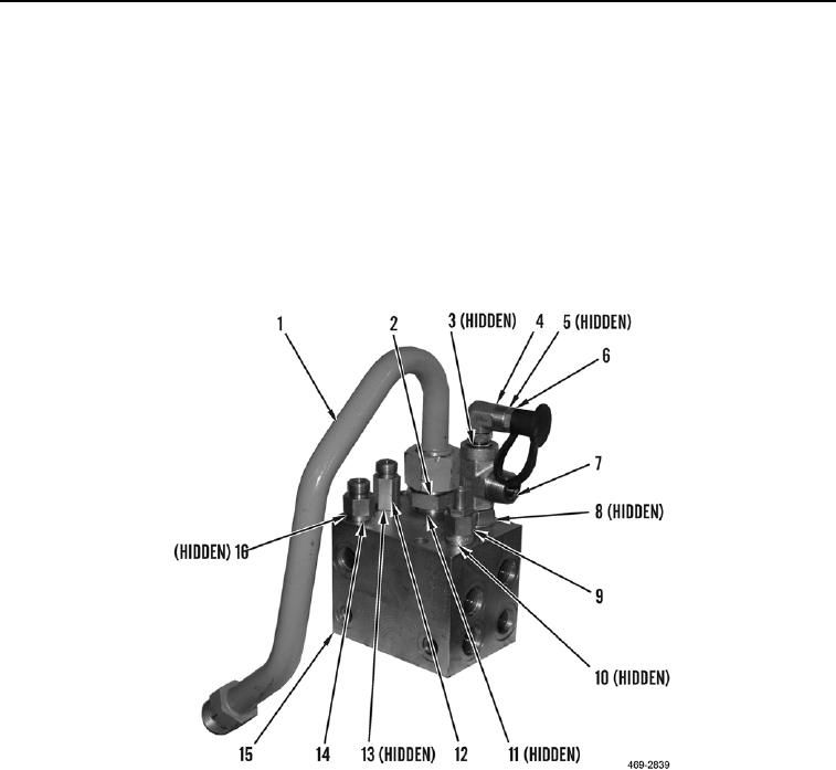
10. Remove piston pump hydraulic oil supply line (Figure 7, Item 1), fitting (Figure 7, Item 2) and two O-rings
(Figure 7, Item 11) from hydraulic fan and brake control manifold (Figure 7, Item 15). Discard O-rings.
11. Remove fitting (Figure 7, Item 14) and two O-rings (Figure 7, Item 16) from hydraulic fan and brake control
manifold (Figure 7, Item 15). Discard O-rings.
12. Remove fitting (Figure 7, Item 12) and two O-rings (Figure 7, Item 13) from hydraulic fan and brake control
manifold (Figure 7, Item 15). Discard O-rings.
13. Remove quick disconnect (Figure 7, Item 6), O-ring (Figure 7, Item 5), fitting (Figure 7, Item 4), O-ring
(Figure 7, Item 3), fitting (Figure 7, Item 7) and two O-rings (Figure 7, Item 8) from hydraulic fan and brake
control manifold (Figure 7, Item 15). Discard O-rings.
14. Remove relief valve (Figure 7, Item 9) and two O-rings (Figure 7, Item 10) from hydraulic fan and brake control
manifold (Figure 7, Item 15). Discard O-rings.
Figure 7. Supply Lines.
0231
END OF TASK

