
TM 5-3805-293-23-4
0231
DISASSEMBLY CONTINUED
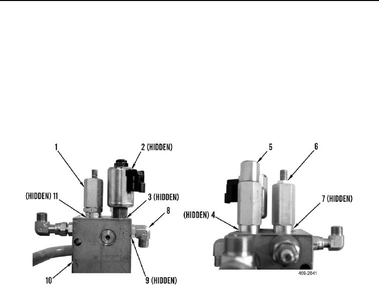
5. Remove diverter valve (Figure 6, Item 5) and three O-rings (Figure 6, Item 4) from hydraulic fan and brake
control manifold (Figure 6, Item 10). Discard O-rings.
6. Remove relief valve (Figure 6, Item 1) and two O-rings (Figure 6, Item 11) from hydraulic fan and brake control
manifold (Figure 6, Item 10). Discard O-rings.
7. Remove relief valve (Figure 6, Item 6) and four O-rings (Figure 6, Item 7) from hydraulic fan and brake control
manifold (Figure 6, Item 10). Discard O-rings.
8. Remove solenoid valve (Figure 6, Item 2) and three O-rings (Figure 6, Item 3) from hydraulic fan and brake
control manifold (Figure 6, Item 10). Discard O-rings.
9. Remove fitting (Figure 6, Item 8) and O-ring (Figure 6, Item 9) from hydraulic fan and brake control manifold
(Figure 6, Item 10). Discard O-ring.
Figure 6. Control Valves.
0231

