
TM 5-3805-293-23-4
0227
INSTALLATION CONTINUED
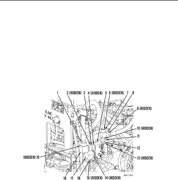
16. Install new O-ring (Figure 11, Item 2) and elbow (Figure 11, Item 18) on check valve (Figure 11, Item 3).
17. Install new O-ring (Figure 11, Item 4) and check valve (Figure 11, Item 3) on implement and steering control
manifold (Figure 11, Item 5).
18. Install new O-ring (Figure 11, Item 15) and connect hydraulic hose (Figure 11, Item 16) to elbow (Figure 11,
Item 17).
19. Install new O-ring (Figure 11, Item 14) and elbow (Figure 11, Item 17) on implement and steering control
manifold (Figure 11, Item 5).
20. Install new O-ring (Figure 11, Item 9) and connect hydraulic hose (Figure 11, Item 8) to tee (Figure 11, Item 11).
21. Install new O-ring (Figure 11, Item 6) and connect hydraulic tube (Figure 11, Item 7) to tee (Figure 11, Item 11).
22. Install new O-ring (Figure 11, Item 10) and install tee (Figure 11, Item 11) to check valve (Figure 11, Item 12).
23. Install new O-ring (Figure 11, Item 13) and check valve (Figure 11, Item 12) on implement and steering control
manifold (Figure 11, Item 5).
24. Install new O-ring (Figure 11, Item 19) and connect hydraulic hose (Figure 11, Item 1) to elbow (Figure 11,
Item 18).
Figure 11. Hydraulic Hose Connections.
0227

