
TM 5-3805-293-23-4
0228
REMOVAL CONTINUED
000228
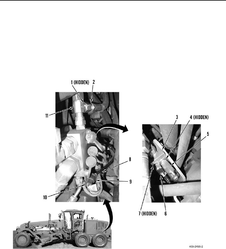
3. Remove hose (Figure 3, Item 2) and O-ring (Figure 3, Item 1) from tee fitting (Figure 3, Item 11). Discard
O-ring.
4. Remove pressure relief valve (Figure 3, Item 5) and O-ring (Figure 3, Item 4) from implement steering control
manifold (Figure 3, Item 3). Discard O-ring.
5. Remove tiedown strap (Figure 3, Item 8) from rear chassis wiring harness (Figure 3, Item 10). Discard tiedown
strap.
6. Disconnect electrical connector (Figure 3, Item 9) from rear chassis wiring harness (Figure 3, Item 10).
7. Remove main hydraulic pump discharge pressure sensor (Figure 3, Item 6) and O-ring (Figure 3, Item 7) from
implement steering control manifold (Figure 3, Item 3). Discard O-ring.
Figure 3. Pressure Sensor.
00228
END OF TASK

