
TM 5-3805-293-23-4
0227
INSTALLATION CONTINUED
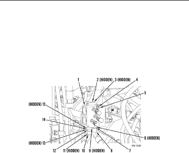
4. Install implement and steering control manifold (Figure 9, Item 1) on machine.
5. Install new O-ring (Figure 9, Item 15) and connector (Figure 9, Item 14) on implement and steering control
manifold (Figure 9, Item 1).
6. Install washer (Figure 9, Item 3), bolts (Figure 9, Item 2), washer (Figure 9, Item 4), and nut (Figure 9, Item 5),
on implement and steering control manifold (Figure 9, Item 1).
7. Install new O-ring (Figure 9, Item 13) and check valve (Figure 9, Item 12) on connector (Figure 9, Item 14).
8. Install new O-ring (Figure 9, Item 9) and hydraulic hose (Figure 9, Item 8) on connector (Figure 9, Item 7).
9. Install new O-ring (Figure 9, Item 6) and connector (Figure 9, Item 7) on implement and steering control
manifold (Figure 9, Item 1).
10. Install new O-ring (Figure 9, Item 11) and connect hydraulic hose (Figure 9, Item 10) to check valve (Figure 9,
Item 12).
Figure 9. Lower Hydraulic Hose Connections.
0227

