
TM 5-3805-293-23-4
0227
ASSEMBLY
000227
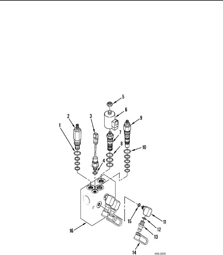
1. Install five new O-rings (Figure 7, Item 10) and regulating valve (Figure 7, Item 9) on implement and steering
control manifold (Figure 7, Item 16). Torque to 44 5 lb-ft (60 7 Nm).
2. Install new O-ring (Figure 7, Item 4) and hydraulic discharge pressure sensor (Figure 7, Item 3) on implement
and steering control manifold (Figure 7, Item 16). Torque to 15 2 lb-ft (20 2 Nm).
3. Install three new O-rings (Figure 7, Item 8) and cartridge (Figure 6, Item 7), coil (Figure 6, Item 6), and nut
(Figure 6, Item 5) on implement and steering control manifold (Figure 7, Item 16). Torque to 37 lb-ft (50 Nm).
4. Install three new O-rings (Figure 7, Item 15) and fittings (Figure 7, Item 11) on implement and steering control
manifold (Figure 7, Item 16).
5. Install three new O-rings (Figure 7, Item 12), test fittings (Figure 7, Item 13) and dust covers (Figure 7, Item 14)
on implement and steering control manifold (Figure 7, Item 16).
6. Install four new O-rings (Figure 7, Item 1) and relief valve (Figure 7, Item 2) on implement and steering control
manifold (Figure 7, Item 16). Torque to 37 lb-ft (50 Nm).
Figure 7. Implement and Steering Control Manifold.
0227
END OF TASK

