
TM 5-3805-293-23-4
0227
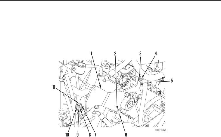
REMOVAL CONTINUED
24. Remove nut (Figure 5, Item 7), washer (Figure 5, Item 11), bolt (Figure 5, Item 10), washer (Figure 5, Item 9),
and clamp (Figure 5, Item 8) from plate (Figure 5, Item 1).
25. Remove bolt (Figure 5, Item 4), washer (Figure 5, Item 3), and clamp (Figure 5, Item 5) from plate (Figure 5,
Item 1).
26. Remove three bolts (Figure 5, Item 6), washers (Figure 5, Item 2), and plate (Figure 5, Item 1) from machine.
Figure 5. Implement and Steering Control Manifold Plate.
0227
END OF TASK
DISASSEMBLY
000227
1. Remove relief valve (Figure 6, Item 2) and four O-rings (Figure 6, Item 1) from implement and steering control
manifold (Figure 6, Item 16). Discard O-rings.
2. Remove regulating valve (Figure 6, Item 9) and five O-rings (Figure 6, Item 10) from implement and steering
control manifold (Figure 6, Item 16). Discard O-rings.
3. Remove hydraulic discharge pressure sensor (Figure 6, Item 3) and O-ring (Figure 6, Item 4) from implement
and steering control manifold (Figure 6, Item 16). Discard O-ring.
4. Remove nut (Figure 6, Item 5), implement pilot pressure supply solenoid coil (Figure 6, Item 6), cartridge
(Figure 6, Item 7), and three O-rings (Figure 6, Item 8) from implement and steering control manifold (Figure 6,
Item 16). Discard O-rings.
5. Remove three dust caps (Figure 6, Item 14), test fittings (Figure 6, Item 13) and O-rings (Figure 6, Item 12)
from implement and steering control manifold (Figure 6, Item 16). Discard O-rings.
6. Remove three fittings (Figure 6, Item 11) and O-rings (Figure 6, Item 15) from implement and steering control
manifold (Figure 6, Item 16). Discard O-rings.

