
TM 5-3805-293-23-4
0223
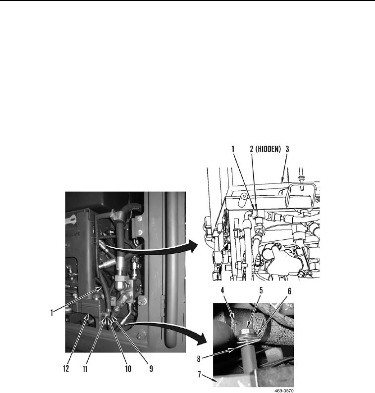
REMOVAL CONTINUED
000223
4. Remove bolt (Figure 3, Item 5), washer (Figure 3, Item 6), and two clips (Figure 3, Item 4 and 8) from frame
(Figure 3, Item 7).
5. Remove bolt (Figure 3, Item 10), washer (Figure 3, Item 11), and clip (Figure 3, Item 9) from hydraulic service
base (Figure 3, Item 12).
N OT E
If may be necessary to disconnect hoses or remove clamps from hoses to gain clear
access to fittings under hydraulic service pack.
6. Disconnect hose (Figure 3, Item 1), and remove O-ring (Figure 3, Item 2) from hydraulic service tank (Figure 3,
Item 3). Discard O-ring. Remove hose from machine.
Figure 3. Drain Hose.
0223
END OF TASK

