
TM 5-3805-293-23-4
0222
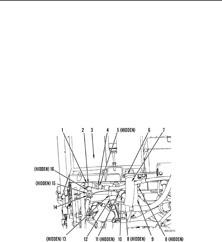
INSTALLATION CONTINUED
N OT E
Hydraulic service pack bracket is shown partially removed for clarity.
7. Install hose (Figure 19, Item 7) and clamp (Figure 19, Item 6) on hydraulic tank (Figure 19, Item 3).
8. Install new O-ring (Figure 19, Item 13) and hydraulic line (Figure 19, Item 12) on hydraulic tank (Figure 19,
Item 3).
9. Install new O-ring (Figure 19, Item 11) and hydraulic line (Figure 19, Item 10) on hydraulic tank (Figure 19,
Item 3).
10. Install new O-ring (Figure 19, Item 5) and hydraulic line (Figure 19, Item 4) on hydraulic tank (Figure 19,
Item 3).
11. Install new O-ring (Figure 19, Item 2) and hydraulic line (Figure 19, Item 1) on hydraulic tank (Figure 19,
Item 3).
12. Install new O-ring (Figure 19, Item 15) and hydraulic line (Figure 19, Item 14) on hydraulic tank (Figure 19,
Item 3).
13. Install hose (Figure 19, Item 9) and two clamps (Figure 19, Item 8) on hydraulic tank (Figure 19, Item 3) and
implement and steering pump (Figure 19, Item 16).
Figure 19. Hydraulic Hoses to Hydraulic Tank.
0222

