
TM 5-3805-293-23-4
0223
INSTALLATION
000223
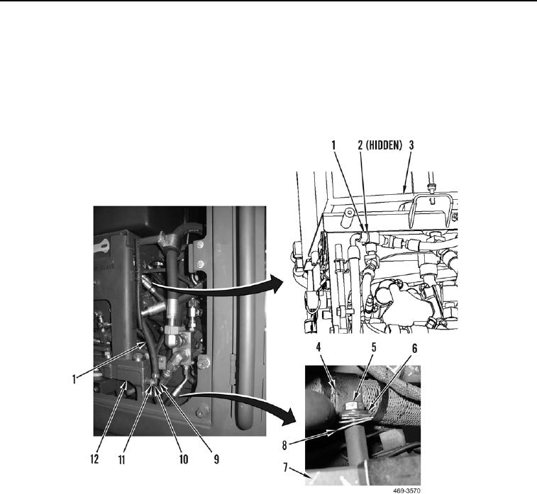
1. Position hose (Figure 5, Item 1) on machine. Install new O-ring (Figure 5, Item 2) and hose on hydraulic
service tank (Figure 5, Item 3).
2. Install clip (Figure 5, Item 9), washer (Figure 5, Item 11), and bolt (Figure 5, Item 10) on hydraulic service base
(Figure 5, Item 12).
3. Install two clips (Figure 5, Item 4 and 8), washer (Figure 5, Item 6), and bolt (Figure 5, Item 5), on frame
(Figure 5, Item 7).
Figure 5. Drain Hose.
0223

