
TM 5-3805-293-23-4
0223
INSTALLATION CONTINUED
000223
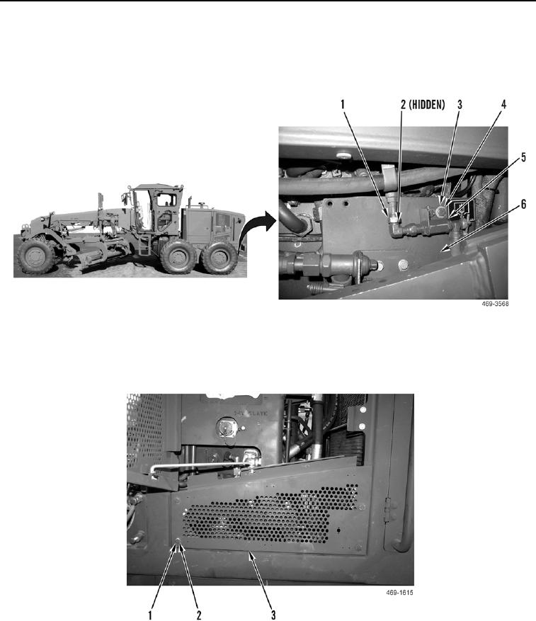
4. Install valve (Figure 6, Item 5), two washers (Figure 6, Item 4) and bolts (Figure 6, Item 3) on cover (Figure 6,
Item 6).
5. Install new O-ring (Figure 6, Item 2) and connect hose (Figure 6, Item 1) to drain valve (Figure 6, Item 5).
Figure 6. Hose and Valve.
0223
6. Install left rear access cover (Figure 7, Item 3), four washers (Figure 7, Item 2), and bolts (Figure 7, Item 1) on
engine enclosure.
Figure 7. Left Rear Access Cover.
0223
END OF TASK

