
TM 5-3805-293-23-4
0188
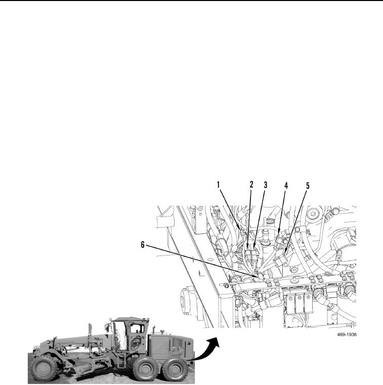
INSTALLATION CONTINUED
N OT E
Coolant hose removed in Figure 43 to show locations of connections.
48. Connect rear chassis wiring harness (Figure 43, Item 6) to solenoid wiring harness connector (Figure 43,
Item 2).
49. Connect rear chassis wiring harness (Figure 43, Item 6) to oil temp/park brake wiring harness connector
(Figure 43, Item 3).
50. Connect rear chassis wiring harness (Figure 43, Item 6) to speed sensor wiring harness connector (Figure 43,
Item 5).
51. Connect rear chassis wiring harness (Figure 43, Item 6) to hydraulic valve wiring harness connector
(Figure 43, Item 4).
52. Connect rear chassis wiring harness (Figure 43, Item 6) to pump pressure sensor connector (Figure 43,
Item 1).
Figure 43. Harness In-Line Connections.
0188
Change 1

