
TM 5-3805-293-23-4
0188
INSTALLATION CONTINUED
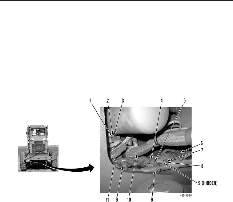
N OT E
Cooling module removed in Figure 44 to show locations of connections.
53. Install three rear chassis ground eyelets (Figure 44, Item 9), washer (Figure 44, Item 8), and bolt (Figure 44,
Item 7) on frame.
54. Install rear chassis wiring eyelet (Figure 44, Item 3), and nut (Figure 44, Item 2) on pressure switch (Figure 44,
Item 1).
55. Install four clamps (Figure 44, Item 6), three washers (Figure 44, Item 5), and bolts (Figure 44, Item 4) on rear
chassis wiring harness (Figure 44, Item 10) and frame.
56. Connect rear chassis wiring harness (Figure 44, Item 10) to rear lighting harness connector (Figure 44,
Item 11).
Figure 44. Rear Ground Connections.
0188
Change 1

