
TM 5-3805-293-23-4
0188
INSTALLATION CONTINUED
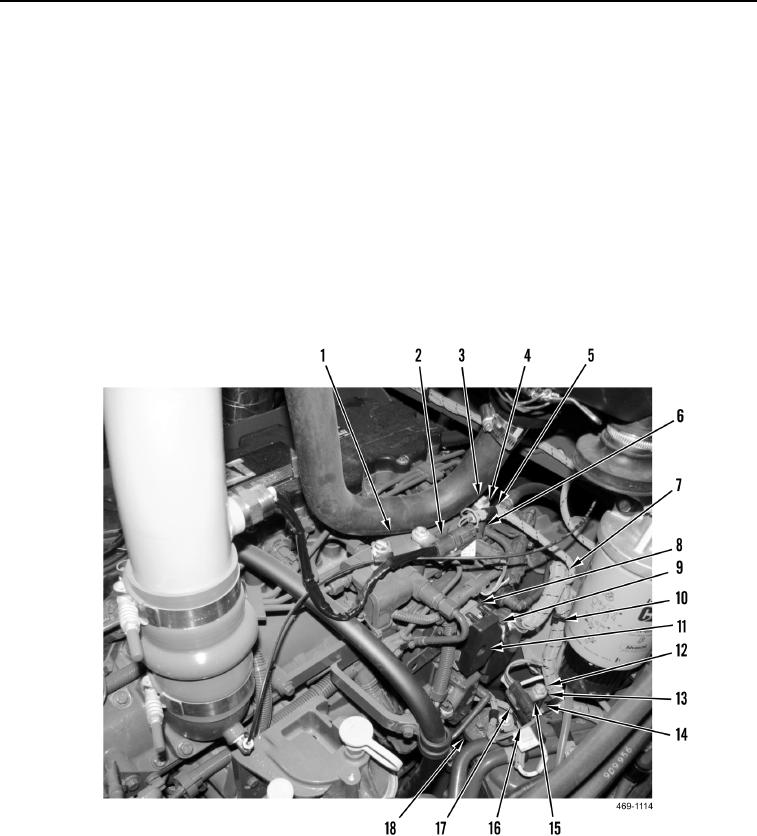
39. Install spacer (Figure 41, Item 14), three clips (Figure 41, Item 15), washer (Figure 41, Item 13), and bolt
(Figure 41, Item 12) on transmission cooler bracket (Figure 41, Item 18).
40. Connect rear chassis wiring harness (Figure 41, Item 7) to starter relay harness connector (Figure 41, Item 16)
and install on clip (Figure 41, Item 15).
41. Connect rear chassis wiring harness (Figure 41, Item 7) to charge pressure harness connector (Figure 41,
Item 17) and install on clip (Figure 41, Item 15).
42. Connect rear chassis wiring harness connector (Figure 41, Item 9) to engine ECM (Figure 41, Item 8) and
tighten bolt (Figure 41, Item 11).
43. Install spacer (Figure 41, Item 6), clamp (Figure 41, Item 5), washer (Figure 41, Item 4), and bolt (Figure 41,
Item 3) on rear chassis wiring harness (Figure 41, Item 7) and fuel rail (Figure 41, Item 1).
44. Connect rear chassis wiring harness (Figure 41, Item 7) to intake air temperature sensor connector (Figure 41,
Item 2).
45. Install new tiedown straps (Figure 41, Item 10) on rear chassis wiring harness (Figure 41, Item 7).
Figure 41. Engine ECM Connection.
0188
Change 1

