
TM 5-3805-293-23-4
0188
INSTALLATION CONTINUED
N OT E
Route rear chassis wiring harness as noted during removal.
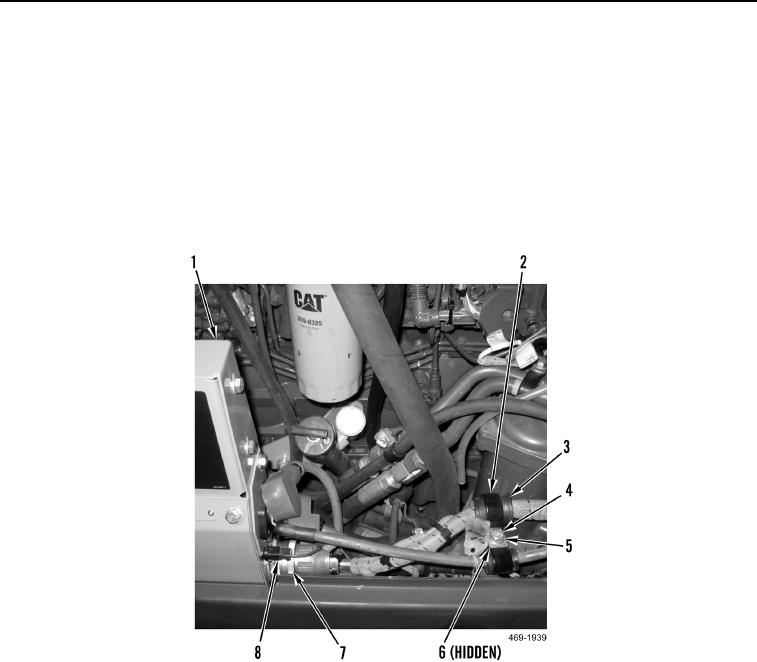
33. Connect rear chassis wiring harness twist lock connector (Figure 38, Item 7) to circuit breaker box (Figure 38,
Item 1).
34. Connect rear chassis wiring harness connector (Figure 38, Item 8) to circuit breaker box (Figure 38, Item 1).
35. Install spacer (Figure 38, Item 6), two grommets (Figure 38, Item 3), clamps (Figure 38, Item 2), washer (Figure
38, Item 5), and bolt (Figure 38, Item 4) on enclosure.
Figure 38. Circuit Breaker Box Connections.
0188
Change 1

