
TM 5-3805-293-23-4
0188
INSTALLATION CONTINUED
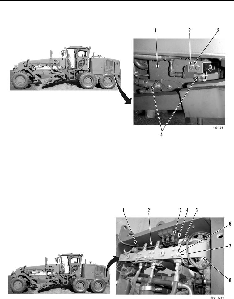
64. Install two drain valve assemblies (Figure 48, Item 4), four washers (Figure 48, Item 3), and bolts (Figure 48,
Item 2) on solenoid cover (Figure 48, Item 1).
Figure 48. Drain Valve.
0188
N OT E
Cooling module removed in Figure 49 to show locations of connections.
65. Install rear chassis ground eyelet (Figure 49, Item 7), washer (Figure 49, Item 6), and bolt (Figure 49, Item 5)
on bracket (Figure 49, Item 8).
66. Connect three rear chassis wiring harness connectors (Figure 49, Item 4) to relays (Figure 49, Item 3).
67. Install new tiedown straps (Figure 49, Item 1) on rear chassis wiring harness (Figure 49, Item 2).
Figure 49. Relay Connections.
0188
Change 1

