
TM 5-3805-293-23-4
0170
INSTALLATION CONTINUED
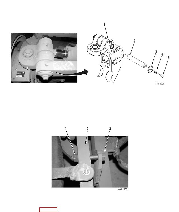
6. Install pin (Figure 8, Item 2), two retainers (Figure 8, Item 3), washers (Figure 8, Item 4), and bolts (Figure 8,
Item 5) on wheel lean cylinder (Figure 8, Item 1). Torque to 148 lb-ft (200 Nm).
Figure 8. Wheel Lean Cylinder Pin Installation.
0170
WARN I N G
If wheels are not installed on machine, do not remove wheel lean lock bolt from front axle.
Failure to follow this warning may result in injury or death to personnel.
7. Remove nut (Figure 9, Item 1) and wheel lean lock bolt (Figure 9, Item 3) from front axle (Figure 9, Item 2).
Figure 9. Wheel Lean Lock Bolt.
0170
8. Remove supports, and lower the front of machine to the ground.
9. Remove vacuum cap (WP 0221).
END OF TASK
END OF WORK PACKAGE

