
TM 5-3805-293-23-4
0171
REMOVAL CONTINUED
N OT E
Note position of hoses prior to removal from blocks to aid in installation.
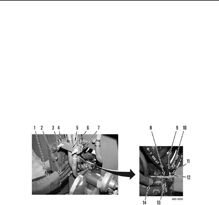
3. Remove two locknuts (Figure 3, Item 3), washers (Figure 3, Item 4), plate (Figure 3, Item 6) and two blocks
(Figure 3, Item 7) from hose assembly (Figure 3, Item 5) on left side of machine. Discard locknuts.
4. Pull protective cover (Figure 3, Item 1) away from hose clamps (Figure 3, Item 14) to expose hose bundles
(Figure 3, Item 2) on left side of machine.
5. Repeat steps 3 and 4 on right side of machine.
6. With assistance, position hose bundles (Figure 3, Items 2 and 5) aside as necessary and remove block (Figure
3, Item 10) from two studs (Figure 3, Item 9).
N OT E
To maintain hose and block positioning for installation, pry up on bottom block and install
tiedown strap around lower hose bundle and block.
7. Remove two locknuts (Figure 3, Item 11), washers (Figure 3, Item 12), plate (Figure 3, Item 8), and blocks
(Figure 3, Item 13) from studs (Figure 3, Item 9) and hose bundles (Figure 3, Items 2 and 5). Discard locknuts.
Figure 3. AWD Hydraulic Hose Assembly.
0171

