
TM 5-3805-293-23-3
0164
REMOVAL CONTINUED
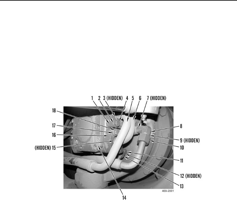
18. Disconnect hydraulic hose (Figure 10, Item 10) and remove O-ring (Figure 10, Item 9) from AWD piston motor
(Figure 10, Item 14). Discard O-ring.
19. Disconnect hydraulic hose (Figure 10, Item 13) and remove fitting (Figure 10, Item 11) and two O-rings (Figure
10, Item 12) from AWD piston motor (Figure 10, Item 14). Discard O-rings.
20. Remove four bolts (Figure 10, Item 18), washers (Figure 10, Item 17), two clamps (Figure 10, Item 16), hose
(Figure 10, Item 6), and O-ring (Figure 10, Item 15) from AWD piston motor (Figure 10, Item 14). Discard O-
ring.
21. Remove fitting (Figure 10, Item 8) and O-ring (Figure 10, Item 7) from AWD piston motor (Figure 10, Item 14).
Discard O-ring.
22. Remove four bolts (Figure 10, Item 4), washers (Figure 10, Item 2), two clamps (Figure 10, Item 1), hose
(Figure 10, Item 5), and O-ring (Figure 10, Item 3) from AWD piston motor (Figure 10, Item 14) Discard O-ring.
Figure 10. All-Wheel Drive Piston Motor Tube and Line.
0164
23. Position hydraulic hoses aside.
Change 1