
TM 5-3805-293-23-3
0164
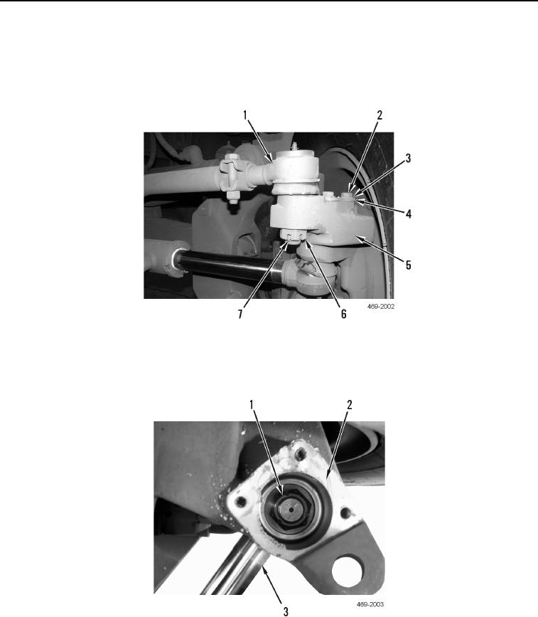
REMOVAL CONTINUED
12. Remove cotter pin (Figure 7, Item 7), nut (Figure 7, Item 6), and steering link (Figure 7, Item 1) from wheel
spindle (Figure 7, Item 5). Discard cotter pin. Position steering link aside.
13. Remove three bolts (Figure 7, Item 2), washers (Figure 7, Item 3), and cover (Figure 7, Item 4) from wheel
spindle (Figure 7, Item 5).
Figure 7. Steering Link and Cover.
0164
14. Remove nut (Figure 8, Item 1) and steering cylinder (Figure 8, Item 3) from wheel spindle (Figure 8, Item 2).
Position steering cylinder aside.
Figure 8. Steering Cylinder.
0164
Change 1