
TM 5-3805-293-23-3
0164
INSTALLATION CONTINUED
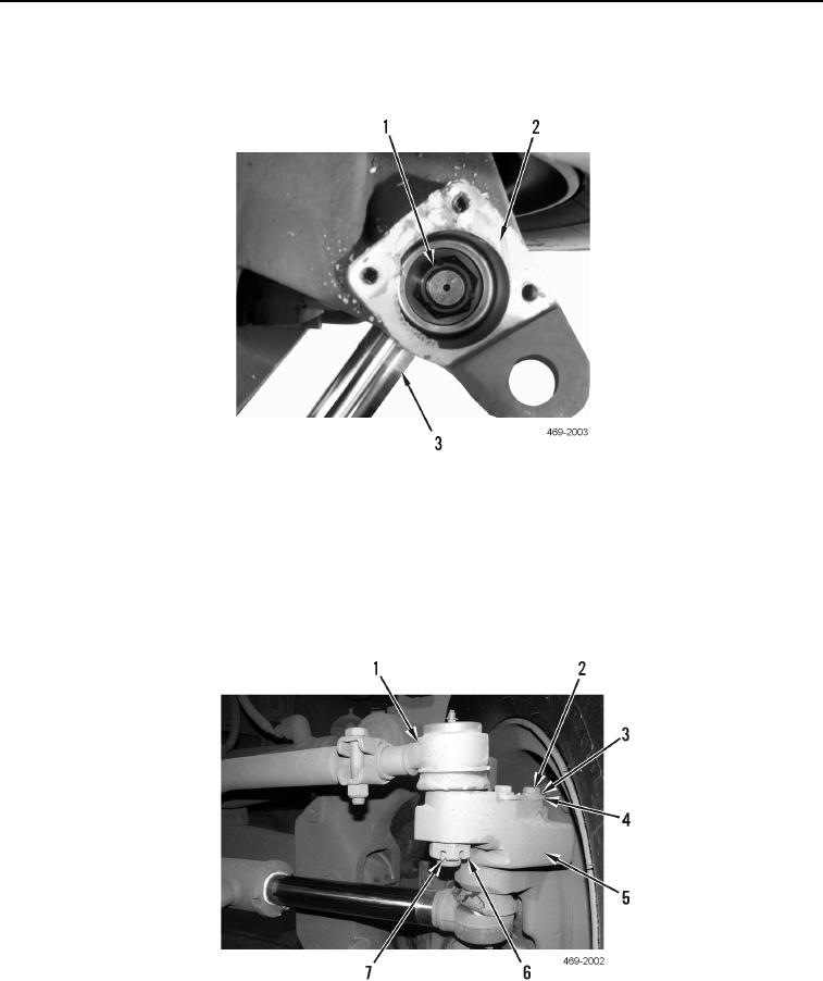
14. Position steering cylinder on machine. Install steering cylinder (Figure 15, Item 3) and nut (Figure 15, Item 1)
on wheel spindle (Figure 15, Item 2). Torque to 162 lb-ft 10 (Nm).
Figure 15. Steering Cylinder.
0164
15. Apply a light coat of silicone sealant to cover (Figure 16, Item 4).
16. Install cover (Figure 16, Item 4), three washers (Figure 16, Item 3), and bolts (Figure 16, Item 2) on wheel
spindle (Figure 16, Item 5).
17. Position steering link (Figure 16, Item 1) on machine. Install steering link, nut (Figure 16, Item 6), and new
cotter pin (Figure 16, Item 7) on wheel spindle (Figure 16, Item 5).
Figure 16. Steering Link and Cover.
0164
Change 1