
TM 5-3805-293-23-3
0131
ASSEMBLY
000131
N OT E
Install fittings as noted at removal.
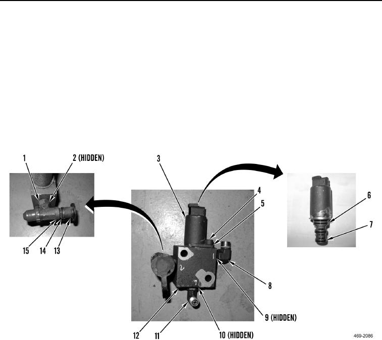
1. Install four new O-rings (Figure 6, Item 7 and 6), solenoid valve (Figure 6, Item 3), clamp bracket (Figure 6,
Item 5) and allen bolt (Figure 6, Item 4) on manifold (Figure 6, Item 12).
2. Install new O-ring (Figure 6, Item 10) and elbow (Figure 6, Item 11) on manifold (Figure 6, Item 12).
3. Install new O-ring (Figure 6, Item 9) and elbow (Figure 6, Item 8) on manifold (Figure 6, Item 12).
4. Install new O-ring (Figure 6, Item 2) and tee boss (Figure 6, Item 1) on manifold (Figure 6, Item 12).
5. Install new O-ring (Figure 6, Item 15), coupling (Figure 6, Item 14) and cap (Figure 6, Item 13), from manifold
(Figure 6, Item 12).
Figure 6. Solenoid Valve.
00131
N OT E
Install lines and hoses as tagged at removal.