
TM 5-3805-293-23-3
0132
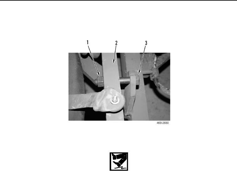
REMOVAL
000132
1. Install wheel lean lock bolt (Figure 1, Item 3) and nut (Figure 1, Item 1) on front axle (Figure 1, Item 2). Hand
tighten only.
Figure 1. Wheel Lean Lock Bolt.
0132
WARN I N G
Lubricating oil is very slippery. Immediately wipe up any spills. Failure to follow this
warning may cause injury to personnel.
N OT E
Tag and mark lines to aid in installation.
Plug or cap all lines to prevent contamination.
1. Remove nut (Figure 2, Item 27), washer (Figure 2, Item 28), bolt (Figure 2, Item 2), washer (Figure 2, Item 3)
and two clamps (Figure 2, Item 4) from hoses (Figure 2, Item 20 and 29).
2. Remove nut (Figure 2, Item 5), washer (Figure 2, Item 6), bolt (Figure 2, Item 24), washer (Figure 2, Item 25)
and two clamps (Figure 2, Item 23) from hoses (Figure 2, Item 20 and 29).
3. Remove bolt (Figure 2, Item 21), washer (Figure 2, Item 22), clamp (Figure 2, Item 7) and grommet (Figure 2,
Item 8) from hose (Figure 2, Item 1).
4. Remove bolt (Figure 2, Item 14), washer (Figure 2, Item 15), clamp (Figure 2, Item 11) and grommet (Figure 2,
Item 12) from hose (Figure 2, Item 13).
5. Disconnect hose (Figure 2, Item 1) from fitting (Figure 2, Item 31) and remove O-ring (Figure 2, Item 34). Dis-
card O-ring.
6. Disconnect hose (Figure 2, Item 13) from fitting (Figure 2, Item 18) and remove O-ring (Figure 2, Item 16).
Discard O-ring.
7. Disconnect hose (Figure 2, Item 29) from fitting (Figure 2, Item 31) and remove O-ring (Figure 2, Item 30).
Discard O-ring.