
TM 5-3805-293-23-3
0131
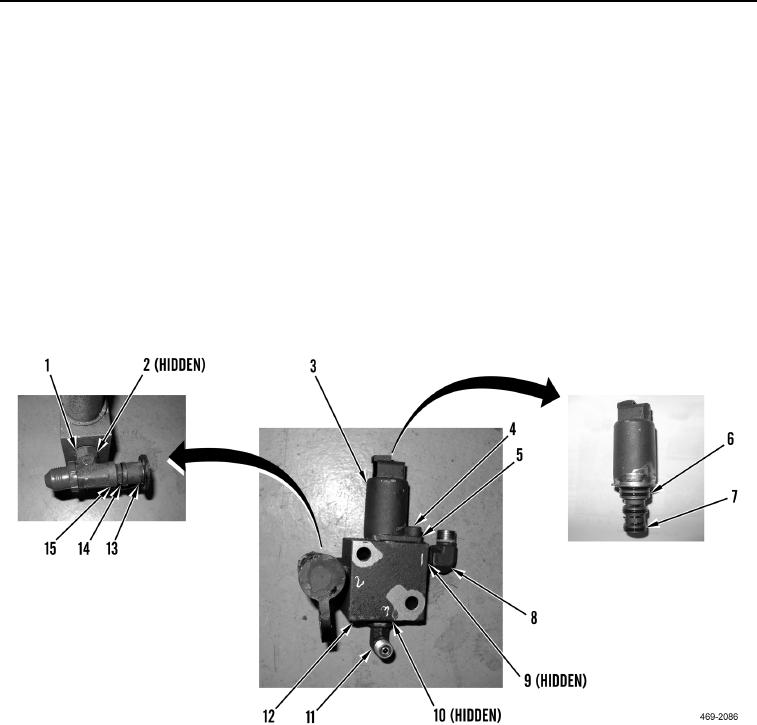
DISASSEMBLY
000131
N OT E
Note position of fittings prior to removal to aid in installation.
1. Remove cap (Figure 5, Item 13), coupling (Figure 5, Item 14) and O-ring (Figure 5, Item 15) from tee boss
(Figure 5, Item 1). Discard O-ring.
2. Remove tee boss (Figure 5, Item 1) and O-ring (Figure 5, Item 2) from manifold (Figure 5, Item 12). Discard O-
ring.
3. Remove elbow (Figure 5, Item 8) and O-ring (Figure 5, Item 9) from manifold (Figure 5, Item 12). Discard O-
ring.
4. Remove elbow (Figure 5, Item 11) and O-ring (Figure 5, Item 10) from manifold (Figure 5, Item 12). Discard O-
ring.
5. Remove allen bolt (Figure 5, Item 4), clamp bracket (Figure 5, Item 5) solenoid valve (Figure 5, Item 3) and
four O-rings (Figure 5, Items 6 and 7) from manifold (Figure 5, Item 12), Discard O-rings.
Figure 5. Solenoid Valve.
00131
END OF TASK
CLEANING AND INSPECTION
000131
1. Clean and inspect all mechanical parts IAW Mechanical General Maintenance Instructions (WP 0346).
2. Clean and inspect all electrical parts IAW Electrical General Maintenance Instructions (WP 0347).
END OF TASK